
It took about a year to complete my first goal of
mixed-band QRP WAS ... at
the bottom of
solar cycle 23!
Along the way, I also managed to get my FISTS CC#, all QRP.
I've been casually entering contests (at QRP power) and have gotten a
few lucky/persistent contacts, leading to WAC.
Now I'm foolish enough to try for DXCC at QRP power ... I have passed
my Extra exam (for that DX window) and am working on code speed.
You can find out about my other radio activities at a
companion page.
Long, long ago I first started studying for my license in 1971, when I was in eighth grade. I learned Morse from a book that taught it via picture mnemonics - R is for Racer, with a drawing of a race car, with the wheels being dit and the body a dah, for .-. and so on. It seemed to work, at least to 5 WPM. I studied the theory from the question pool, and understood most of it.
I never took the test. Mostly it came down to not having any money to spare for the hobby, nor the space to do my own construction. I don't really remember being too disappointed about it. The Novice bands didn't seem that interesting - my interest was in short-distance voice ("phone"), not DX code contacts. You can read the rest of the story at a companion page.
QRP (1) After passing my Technician exam in 2004, I picked up The Joy of QRP in the library and was smitten. I had other projects I wanted to finish first (fat chance!) but started studying Morse again.
Learning Morse Code Again Weak signal DX? That required getting my General license. Which meant learning code - only 5WPM, and the requirement will probably go away (the ITU has already removed it, but the FCC may not act on it until 2006). I don't really mind, much - learning code and communicating on CW seem to be a good link to the origins of the hobby, even if I didn't expect to do it much. Little did I know.
Making contacts
For DX spots,
this site
works pretty well.
When I hear a big mess and don't know why, sometimes
there are clues.
I'm not yet used to listening to the 'DX window', since
it's outside the General bands.
I find Paul
AA6Z's
AZMAP's
very useful for getting an idea of what the
path is really like, and Julian
G4ILO's
HFProp
is an incredibly cool tool
for helping figure out just what I might be able to reach.
QRP (2)
While studying, I found a great deal on an
Elecraft
KX1
transceiver (s/n 1049) on ebay, so I snapped it up.
Alex
NS6Y
had done a great job building it.
I fiddled with it a little, but didn't really have a place
to set up a good antenna and mostly just set it aside.
When I got legal for HF, I started trying to use it.
I made up a relatively small antenna - a 48 foot doublet from
24 gauge zip cord: take 60', split the first 24' and use the
rest as feedline.
This is pretty easy to transport and suits the KX-1 ATU pretty
well, but it took me a while to make my first contact! (See
below for lots more antenna adventures - this one was really
not very good.)
I understand why people say that QRP operation may be frustrating
for the new operator.
Listening to the bands just reinforces how poorly 20/7 code prepares
one for the real world.
Still, I'm learning a lot, including how to use paddles... and
I can no longer count my CW QSOs on one hand!
I've put together a Pelican 1060 case for the KX1 based on the efforts of Mike N2HTT, and J-F VA2VYZ since I hope/plan to take mine mountaintopping in the Sierra and elsewhere. Leigh WA5ZNU has a nice arrangement in a waist-carried bag for less rigorous (more casual?) travel.
WA3WSJ has a nice page collecting several useful changes here, and AE5X has a good discussion of how to get more RF from internal batteries here,
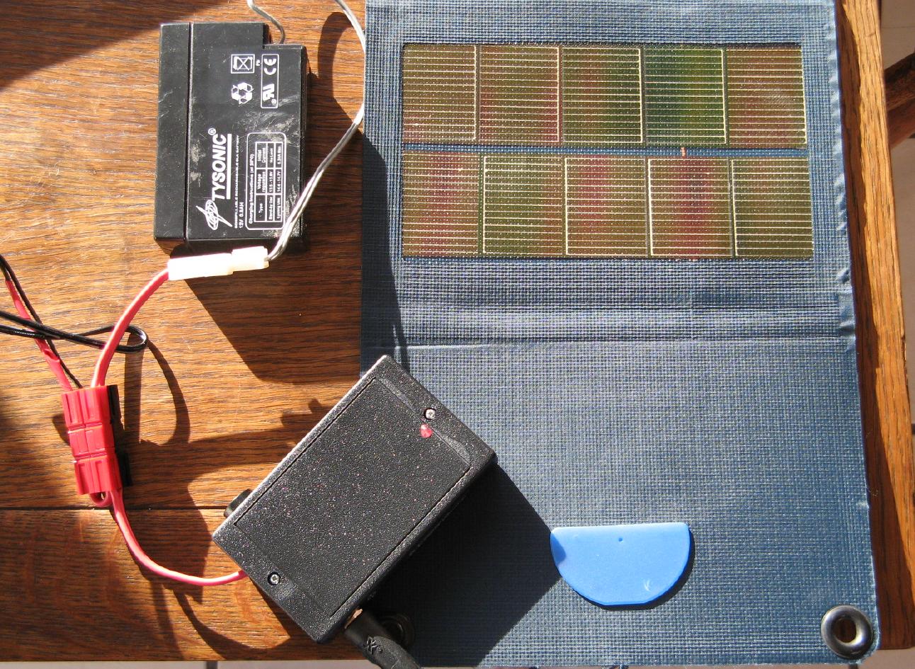
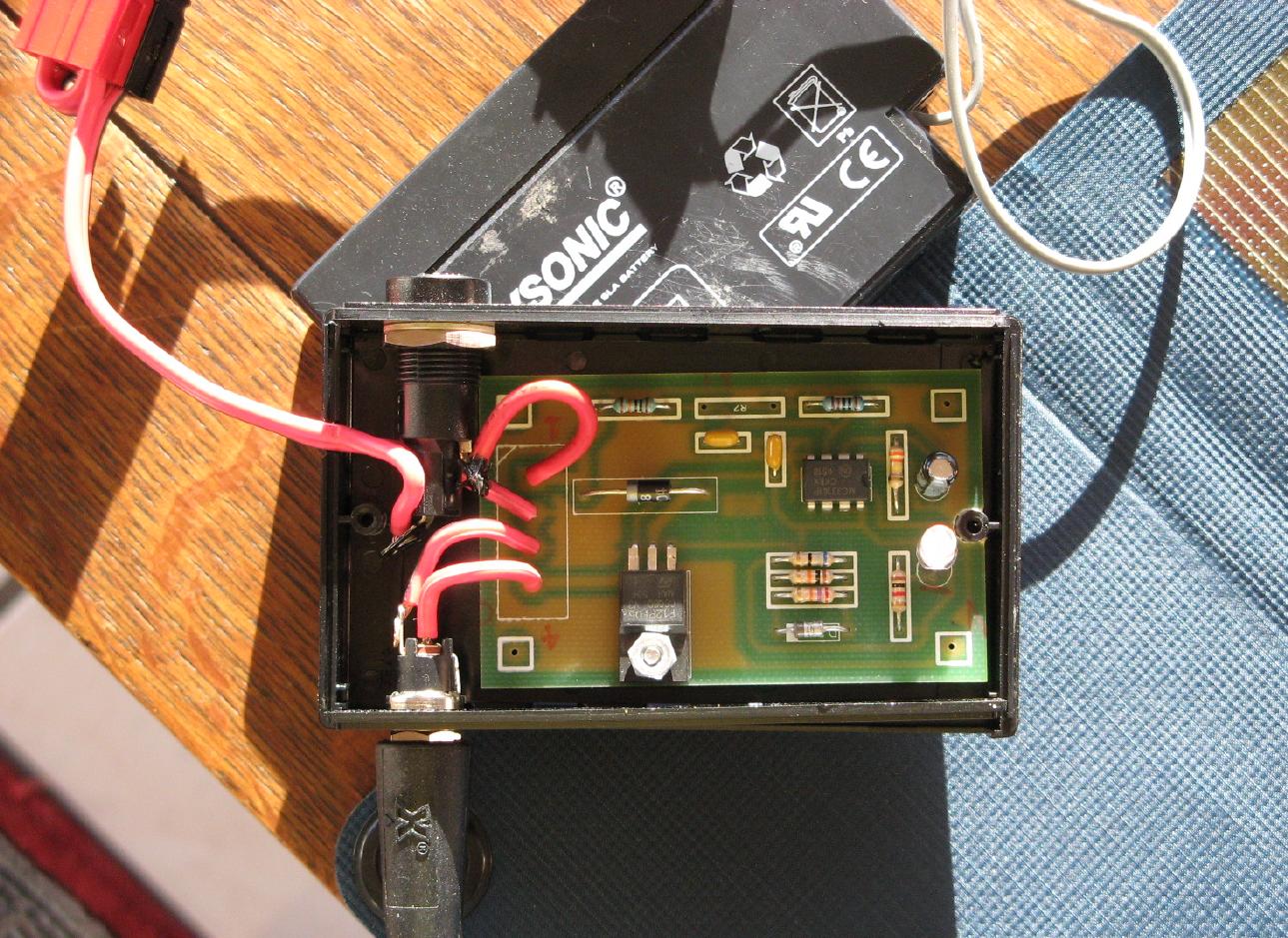
I sometimes power the KX1 with a folding 5W solar panel from Northern Tools. I combined it with a small charge controller from Don KD5NDB. I placed this in a small PacTech enclosure with a fuse and double-ended Powerpole pigtail - one for an SLA, one for the radio. Works a treat.
K2
I like the KX1 a lot, but wanted a more full-featured radio
for my office/operating station..
I started looking for a built
K2
- I have an awful lot of backed
up projects and didn't want to add a big one. I bought s/n 3641
from Chris
VA7CAB;
he did a great job of building the base model,
with only the internal battery option.
I couldn't leave well enough alone:
I added the FDIMP, KNB2, KAT2 and the
strong signal mod.
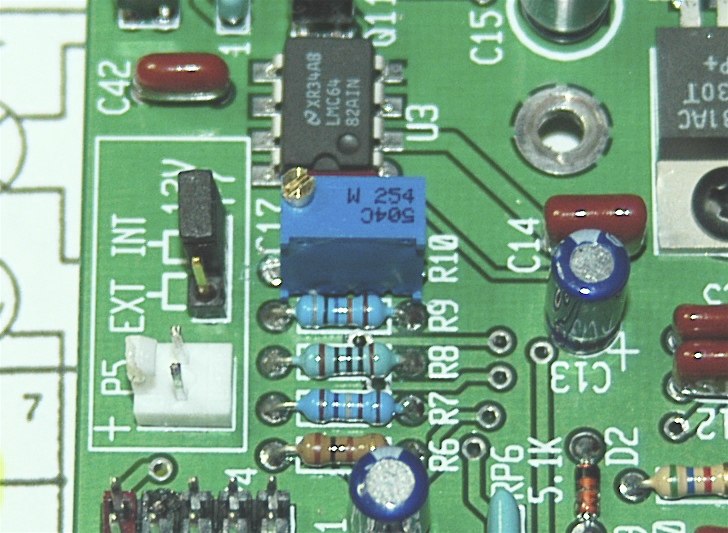
I changed R10 to be a trimpot
(so the internal voltmeter was accurate): you can see a
photo
of this mod, which was quite simple.
I used a Bourns
QRO
The bottom of the solar cycle has not been a lot of fun.
I've made a lot of interesting contacts, but the majority
have been little more than R 599 CA TU or something similar.
I finally decided to add the companion 100W amp to my K2, so
I can engage in some ragchews and actually make contacts in
an emergency.
Mine is mounted in a separate EC2 cabinet, along with the
KAT100 automatic tuner, as described
here and
here.
Running this requires the KIO2 serial interface, which has
the added benefit of computer control of pretty much everything
on the K2!
That's kind of fun, though it feels more like playing a video game
and less like running a radio.
I suspect I'll mostly use it to make logging easier.
Antennas
I also have a lot to learn about antennas for HF.
Cebik
has some of the most approachable tutorials that I've found;
got me going much faster than the ARRL Antenna Handbook,
which is probably better for in-depth study after
grasping the basics.
He has some
detractors, too.
My main QTH is at home, a single story house surrounded by two-story
houses, with a tiny back yard - total lot size is 55x105.
The immediately surrounding trees are only about 20' tall.
So a traditional dipole doesn't really seem to be in the cards.
Doublet
My first antenna was a simple non-resonant doublet, as suggested
for a KX-1 by Bob
NW8L:
I use a simple doublet made from 64 ft. of 18 ga. speaker wire. The
first 24 ft. is split to make halfwave dipole elements on 30 meters,
with the remaining 40 feet serving as a balanced feedline. The KX1 can
tune it on all 3 bands, with good results. Besides vee and sloper
arrangements, I sometimes use it as a single radial vertical... one
element going straight up to a tree limb, the other running above the
ground as the radial with the feedpoint and feedline elevated a foot
or two. I like a longish feedline so that the antenna can be some
distance from the operating position. This is helpful when I want the
antenna setup up at some advantageous but exposed place like a
ridgeline or peak but want to operate down in a more sheltered spot to
avoid wind and/or the blazing NM sun.
NorCal Doublet
The
NorCal Doublet
seems like a slightly more refined version of my zip cord doublet;
I particularly like that the 'feedline' portion has a bit more
isolation between the conductors.
The downside is that ribbon cable is typically 26g - even smaller!
I was all set to spend time trying it out as a 'trail-friendly'
antenna when someone pointed out
this note
and
this page,
both of which made me decide to spend my trail antenna efforts
elsewhere (like
W3EDP).
It appears that the 44' length is really nice from a theoretical
point of view, but if you don't have it 40' in the air, it's more or
less omni, and very difficult to match.
Then again,
Ron
W6AZ's
had
very good experience
with one!
PAC-12
I built up a
PAC-12, which seems
a more likely portable antenna - admittedly, it's a bit more kit
to carry along than just some wire, and it's not inherently
multi-band (switch coils and retune).
It's not very useful in my yard because of the low radiation angle
and surrounding houses.
I took it out to the mountains and made good, if weak, contacts on 20m
and 40m (Iowa and Oklahoma) using 3W from my KX-1.
It checks out reasonably well with an antenna analyzer.
I built a
Tenna Dipper
to pack along with it and help speed tuning - a neat little gizmo!
It has a nice little SWR bridge that tries to balance a 50 ohm resistive
load; a loaded whip vertical like the PAC-12 has a feedpoint
impedance more like 20-30 ohms.
So I added matching transformer right at the feedpoint, using
this design.
I fit it right behind the feedpoint plate; it sticks out a bit, but
isn't really that much more fragile than it was.
I could probably have made it with a smaller diameter core or a
binocular core, to make it more compact, and I may do that at
some point.
It does exactly what I wanted - the impedance with the 20m coil is
R=50 when X=0! With the 40m coil, it's a bit higher, more like R=72
X=0, but that's better than I was getting.
I'll do some more testing and probably some more fiddling with
the ground radials.
Phil
AD5X's
experiments has some other good ideas for
feedpoint matching (see page 45).
W3EDP
W3EDP wrote about
this antenna
in the 30s; there seems to be a lot
of mystique, and a lot of happy users.
The
one analysis
I could find on the web makes it look like a really great antenna.
Interestingly, there is no discussion of this in the ARRL Antenna Book!
But there is a nice collection of articles about the W3EDP and
other antennas
here.
I strung up an 85' wire. With a 17' counterpoise
(elevated off the ground) and a 1:1 balun, my KX-1 could tune up 20/30/40
without too much trouble (1:1 on 20m and 30m, 2:1 on 40m).
The intent is that you get the wire as vertical as possible.
That's not very vertical for me; mine is a sloper from about 30'
to about 15', with the last 6-7' of wire vertical to reach
the balun. This is pretty much the limit for our lot.
The ideal thing is to have the tuner at the feedpoint.
It receives better than the doublet.
The arrangement isn't perfect, because it still takes a moderate
amount of coax to get to my workbench.
Maybe I'll drill a hole in the wall.
(It blew down in the first big storm of the season,
so no drilling happened.)
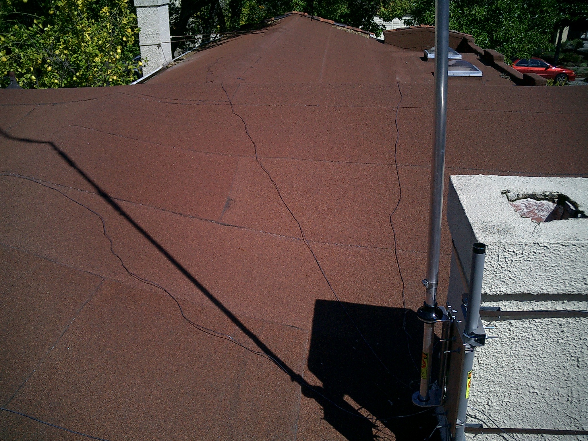
Hustler 'base' vertical
Based on many recommendations, I bought a
Hustler 6-BTV from
DX Engineering.
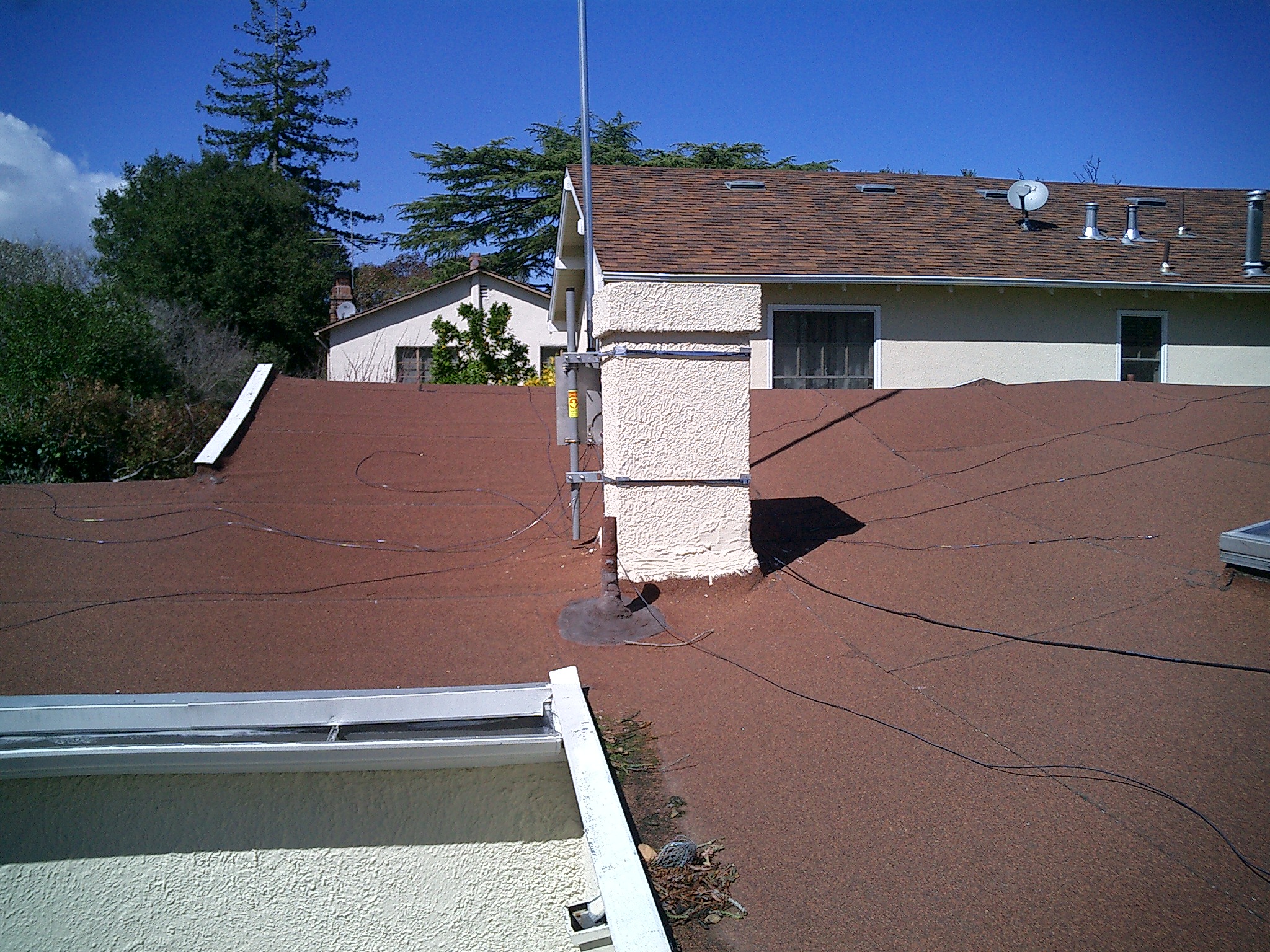
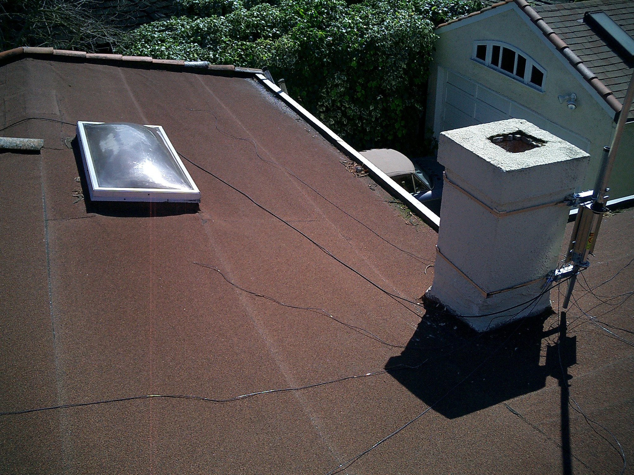
This is mounted to the chimney with a Radio Shack strap mount (made
from the highest quality stamped steel .. or not - various bits deformed
right out of the box).
Andreas
N6NU
brought a tripod over to do some testing after I assembled
it to the rooftop spec: we quickly realized that tuning it on the
ground didn't make any sense.
The antenna is lightweight but quite a handful to manage - we almost lost
it while taking it down!
Hustler's instructions indicate that you can remove the antenna from the
base to do the tuning (which is incremental, per band), but I quickly
realized that I didn't want to do that up on the roof.
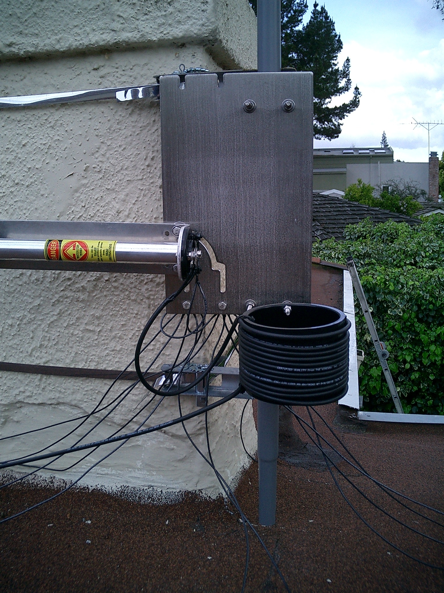
I ordered the
Tilt Base
the next day.
I was unprepared for the weight when it arrived - this thing is
really solid, cut from 1/4" stainless steel plate.
The next time I went up, I added a choke balun, wound on a 4" ABS pipe
coupling.
This blocks common mode currents on the outside of the shield, and
overall reduces the SWR.
It helped a fair bit - I saw sharper and deeper peaks everywhere.
I also rearranged the radials for 20 and got the SWR to be a lot lower.
I tried adding another and that made it worse!
I finally realized that there's one section of the roof that
must be coupling to the 20m radial, so I rearranged them away
from that and it was the improvement I expected.
I had to lengthen the 20m section about an inch to get the dip where I wanted.
Here are the current "final" results:
Horizontal Loop
After some email comments on a few lists, several people convinced me
to try again to get some wire up in the air.
Most recommended a horizontal loop as the secret weapon, and I thought
hard about putting up a 280' loop in Palo Alto.
http://www.arrl.org/members-only/tis/info/pdf/8511020.pdf
Off-Center Fed Dipole
I finally came to the conclusion that I don't have the right set
of supports (trees) on my 50'x105' lot to do this.
I still wanted something for NVIS, though ... so I put up an
OCF dipole.
I "cheated" and bought a pre-built one from
BUXCOMM.
Their 40m-to-6m version, at 66 feet, seemed a likely fit between
my available trees.
Sure enough, I was able to get some antenna rope up with
only about an hour of tossing, fiddling and tying.
It's only up about 30 feet, unfortunately.
I fed it with some low-loss RG-58, with a W1HIS-style common
mode choke at the feedpoint and also at the point where the
coax comes into the house (pretty much like the 6BTV).
The antenna is oriented roughly SW/NE, so it will be interesting
to see just how it works.
It's certainly got less atmospheric noise ... it's
several S-units down from the Hustler when tuning in to WWVB, but
that's just about the worst-case orientation. It's proven to be several
S-units better to Oregon ... and at least one S-unit better from VK2!
Not clear if it was better toVK2.
A complicated radiation pattern, indeed.
W3EDP, again
At the cabin, the location is pretty quiet and the HAAT is such that
a low takeoff angle is not a problem, so I made a more
robust attempt at the W3EDP.
Getting the signal into the shack and providing
suitable grounding
at the second-story operating position are going to be a challenge.
After much urging from Ken
K3VV
("you have gotta, GOT TO get some wire up in the air"),
I got started by stringing 85' of
The Wireman's 18g antenna wire
(CQ532) from
a convenient tree.
I decided to try a slingshot, rather than archery or a spud gun.
I used 30# line and about 2 oz of weight. I
managed to get the fishing line up to the target branch on about
the third try, it didn't snag, it pulled up the antenna rope
(parachute cord from the local army surplus) just fine.
I cut the wire to 85' and my YL pulled on the rope while I
held the end of the wire where it was meant to be.
The usual explanation for a W3EDP is that it's an end-fed Zepp 67
feet long with a 17-ft parallel feedline. (67+17=85). So if this
is true, it's a 40-meter Zepp with a 1/4 wave matching section to
provide a voltage feed at the impedance peak about 17 feet up the
feedline. There are a couple of things wrong with this explanation,
notably that the measured SWRs for the W3EDP are better on bands
above 40 meters than they would be if the antenna actually worked
the way W3EDP thought it did.
If you think of the W3EDP instead as a 102 foot (85+17, G5RV-length)
off-center-fed dipole fed at point 5/6 away from one end and 1/6
away from the other end, then it's a halfwave OCF dipole at ~62
meters with a feedpoint impedance in the neighborhood of 600 ohms
and even-harmonic resonances at 31 and 15.5 meters. This analysis
is provides a better prediction of SWR if you hoist the antenna and
counterpoise into a flat-top dipole or feed it as an OCF inverted
vee.
When you use it in standard W3EDP fashion, you are (for the sake
of convenience) laying 1/6 of your OCF dipole on the ground, and
reasoning that the high-current points are going to be sufficiently
far up the longer section that you can get them in the clear.
There's no expectation that this antenna will perform as well as
a G5RV or an OCF G5RV, but there's the expectation that it will
produce more than half the ERP of the G5RV, if the G5RV flat-top
is at the same height as the midpoint of your 85-foot radiator.
(Neglecting matching system losses.)
I was very happy using the W3EDP on the balcony during the summer
and fall - but in winter, it's not pleasant (yes, we're in California,
but there's snow on the ground...)
I puzzled over how to bring the signal into the house.
The reality is that there should be a tuner at the feedpoint, but
I didn't feel like putting an Elecraft T1 or SGC autotuner there
for the limited use it would get.
Running open wire into the house would be a sure recipe for
RF in the shack.
I ultimately decided to use a 4:1 balun, even though this means
that the antenna isn't really as W3EDP envisioned it.
The KX1 and K2 tune it up just fine, and the signal gets out.
That's all that matters, isn't it?
Inverted L for 160m
Donald
AE6RF
put a bug in my ear about hanging an antenna for "top band"
for the Stew Perry
Topband Distance Challenge.
I figured that there's lots of room at the cabin, wire is
cheap, so why not?
Our trees are about 80' tall, so my plan was to put up
an inverted L with the feedpoint at the upper patio, about
20' up.
It turns out that 20' is an
auspicious number, since it's about 0.05 wavelength.
So we have a rope support at about 75' up which forms the top of the
vertical portion, and then a long run to a tall cedar.
This is 160' in length overall, based on a couple of sites that
indicate that it's better to run the wire long and tune it "shorter"
with a (low-loss) capacitor, rather than having it be short
and have to put in a (higher-loss) inductor.
There's one counterpoise cut to 130' strung at about 20', at
90 degrees to the main radiator.
It's all fed through an Elecraft BL2 4:1 balun.
Putting up all that wire was pretty challenging. I started with the
slingshot again, but really wasn't completely satisfied.
The shot from the deck was high enough, but none of the others
were.
I investigated other mechanisms, and decided that the cheapest
experiment was the
ChuckIt tennis ball launcher.
I drilled a tennis ball for a 5/16" bolt, which I had already
drilled through the head with a
safety wire jig (because I have one, and it's the right tool).
The holes in the bolt head were countersunk to not cut the fishing line.
I unreeled a few hundred feet of fishing line on the ground and
let fly.
Hey! This thing really works! My first shot was at least 20'
higher than I'd managed with the slingshot. It took a few more tries
to get some accuracy, but I found a limb I was satisfied with.
The tennis ball doesn't pass down through the tree as easily as
a couple of fishing weights, but the combination of ball and bolt
worked just fine. I tied the parachute cord to the end and pulled
it back up, then tied the antenna wire insulator to the cord and
pulled the other way.
A few skinny branches broke during this process, so the wire isn't
quite as high as I might like, but it's not bad.
A few other antenna ideas...
N5ESE's
notebook antenna
looks really interesting for travel and I will probably try it
first in the garage where my workbench is.
I seem to operate there more than from my office (at least for now)
and will always have the need for some sort of antenna there.
I hope it will be more useful than a random wire inside my stucco garage...
Linear loaded dipole (Haven't tried this, looks interesting)
Numbers
This seems to be, among other things, a hobby of collecting numbers.
So here are a bunch of mine:
ARSqrp #2085,
FISTS #12284 (CC #1974),
FP #1244,
NAQCC #1348,
QRP QRCI # 12485,
SKCC #2044,
SOC #660;
K2 s/n 3641,
K1 s/n 753,
KX1 s/n 1048.
Last updated 26 Jan 2008
by
cak
I went through the calibration steps to familiarize myself with the unit.
It turned out that the low audio that Chris had reported bugged
me a lot - I ended up spending a lot of time with Gary Surrency at Elecraft
helping via email to try to track this down.
The instructions in the manual are good, but was a tough nut to crack...
I added a KSB2 earlier than I planned, mostly to have a second
crystal filter to test, since the troubleshooting steps seemed
to indicate a problem with the crystal filter.
That ended up being more an issue of my RF probe loading that
part of the circuit too much. Oh well.
With much patient help from Gary, I found a bad
capacitor (C10) in the AGC circuit, that was causing it to act
too strongly when the AGC was on.
That helped, but wasn't the whole story.
We worked through the crystal filter and BFO, finding little problems
along the way, and isolated a problem with the AF amp that I couldn't
track down, so I sent it in for service.
Gary found a broken middle lead on Q7, one of the JFETs that implement
the MUTE switch. When he poked at Q7, the audio came way up.
He said it appeared as if the middle lead had pulled partially out of
the encapsulation... and that he'd never seen this problem before.
That, in itself, made me feel better about not finding it myself!
I added the KDSP2 to get the denoiser, which required a firmware
upgrade. Since I was in there, I added the CW keying mod.
That caused some issues with the power control (ALC) loop.
With help from Don
W3FPR and
this note,
I found value for R98 that made me happier.
It's important to note that the results will vary by band (since
the KAT2's wattmeter isn't completely consistent across the bands)
and that the results when using TUNE/CAL P will be different than
what you see while actually running CW. (That is, I started out
with too high a value for R98, trying to get tight control, but didn't
like the results when running CW, especially on 15m/12m/10m.)
Since I had the K2 open, I decided it was a good time to adopt
Don
W3FPR's
modifications to the KBT2, providing an additional jack
strictly for charging the battery.
I followed his
design
except that I put the jack in one of the existing transverter
holes.
My plan is to get one of the small A&A Smart Chargers and
rig it for 1/4A as well as 1A, and charge the battery on
a regular basis, while running the station of a power supply.
WD8RIF
has collected a lot of QRP antenna discussions
here.
W8JI has
a lot to say
about antennas, baluns, boatanchors, and more.
Everyone, and I mean everyone has their favorite antenna,
the one that works everything they can hear,
over the river, through the woods, across the pole... and no two hams have
the same story, it seems.
I only had 24g zip cord on hand, so I used that.
It wass really not a very good antenna; I found the long feedline to
be a bit cumbersome to keep off the ground.
It was noisy. It was lossy.
But it got me on the air and making a few QSOs;
I ended up making a center support out of schedule 80 PVC
and making an inverted V on the roof of the house, with the
feedline running to my workbench.
Raising it to about 20' cut the noise a fair amount, but
didn't do anything about the loss.
It might be useful to take along for portable ops (without the support).
Radials are a must for an elevated vertical.
I read a number of articles, and found
this
from DXEngineering and
Steve
WB2WIK's
"20 dB for $48.60"
to be most helpful.
I have a small lot, and thus a small roof, but I was determined to
have at least two radials per band as a starting point (the minimum
that Hustler recommends) - except for 80m.
There's just not enough room for those, and I don't care that much (yet).
I spent a happy afternoon on the roof with an MFJ 259 trimming the radials to
resonance and figuring out where I could lay them out.
Once cut to length, I sealed the ends with liquid electrical tape.


I drilled two extra holes in the tilt-base plate to attach them,
similar to the original antenna mount, and ran pigtails from the
two 'extra' ground screws on the antenna base to them.
 Initial results were really quite good. After the initial tuning of 10m,
I had nice dip on 10 and 40, and broad, low SWR on 15 and 30.
In addition, 15 and 30 were fully shortened up.
The broad, low SWR is a bad sign, actually - verticals want to have
a fairly sharp dip. I suspect that these aren't right, or I'm finding
the 'wrong' dip.
20m had a very sharp dip, but the SWR was never lower than 1:1.7.
Initial results were really quite good. After the initial tuning of 10m,
I had nice dip on 10 and 40, and broad, low SWR on 15 and 30.
In addition, 15 and 30 were fully shortened up.
The broad, low SWR is a bad sign, actually - verticals want to have
a fairly sharp dip. I suspect that these aren't right, or I'm finding
the 'wrong' dip.
20m had a very sharp dip, but the SWR was never lower than 1:1.7.
The ideal for the Hustler is apparently fairly low X (capacitance) and
R of about 35 ohms. I knew I would have to go up and add more radials and
do a bit more fiddling. But in the meantime, I managed to operate
on my patio and make some 40m contacts. How nice.
The SWR on 10 and 30 seem a little high, but livable.
I haven't yet bothered to retune 40 since I passed my Extra exam :-)
I didn't mess with 10 more to get the resonant frequency 'just so'
because I don't use that band; the rest of the antenna
was looking OK, so I just left it.
15 and 30 are still fully short.
Some of the bands show a lower SWR at a different frequency, but with higher X.
Band    Target    Final    x    r    SWR    SWR <= 1.5		SWR <= 2
80      3550      3556     9    57   1.22   3545 - 3565		3535 - 3573
40      7100      7095     6    46   1.15   7034 - 7136		6958 - 7162
30      10125     10130    6    38   1.34   10000 - 10170	9956 - 10180
20      14075     14100    6    41   1.3    14000 - 14220	13830 - 14245
15      21100     21010    4    53   1.1    20900 - 21300	20515 - 21350
10      28200     28400    3    32   1.4    28200 - 28600 	28180 - 29995
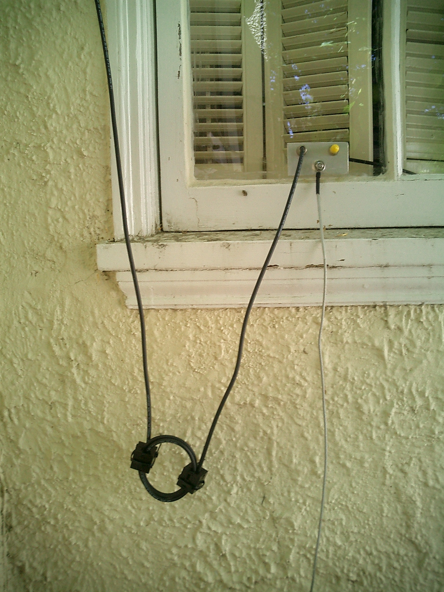 After much debate about just how to get the coax into the house (I expected
to run cable through the crawlspace and up a heating duct), we
realized that we could replace a window pane with acrylic and make
a short, neat run.
So that's what we did - there's a new 8' ground rod right below the
window, and room for another antenna. A 90 degree connector on the
back side of the window lets the RG-8X fit nicely between the window
and shutters.
After reading the article by
Chuck
W1HIS
on
Common-Mode Chokes
I added the snap-on parts you see here - Fair-rite p/n 0443164151,
mix 43, which fits comfortably over three turns of RG-8X.
I'm not sure it makes much of a difference, but I feel better knowing
it's there.
(If you're chasing noise or RFI problems, I also suggest reading
this article
by Jim
K9YC.)
After much debate about just how to get the coax into the house (I expected
to run cable through the crawlspace and up a heating duct), we
realized that we could replace a window pane with acrylic and make
a short, neat run.
So that's what we did - there's a new 8' ground rod right below the
window, and room for another antenna. A 90 degree connector on the
back side of the window lets the RG-8X fit nicely between the window
and shutters.
After reading the article by
Chuck
W1HIS
on
Common-Mode Chokes
I added the snap-on parts you see here - Fair-rite p/n 0443164151,
mix 43, which fits comfortably over three turns of RG-8X.
I'm not sure it makes much of a difference, but I feel better knowing
it's there.
(If you're chasing noise or RFI problems, I also suggest reading
this article
by Jim
K9YC.)
The big downside to a vertical is noise: man-made electrical noise tends
to be vertically polarized, so the Hustler picks it up better than
a doublet or a loop.
My noise situation is not horrible - doesn't move the S-meter except
in the evening on 40m when there is often S3 to S5 noise from
the neighbors.
That's just part of living in the (semi)urban jungle, I guess.
That said ... the antenna certainly works.
I finished QRP-WAS within a year of putting it up
(I had three states before that, via the doublet)
at the bottom of sunspot cycle 23, and have
1000 Miles Per Watt (to ZL on both 20m and 40m), not to
mention VK9 on 80m at 5W (with no radials!).
I completed
WAC
(with 5W) just before the solar flux dropped into the
60s for the last time ... JA, ZL, W6, LU, OH, EA8.
I'm foolish enough to try for QRP DXCC with this setup.
All CW, of course!
http://www.arrl.org/tis/info/Loop-H.html
http://www.arrl.org/members-only/tis/info/pdf/0204047.pdf
http://www.cebik.com/wire/hl.html
http://www.cebik.com/fdim/atl1.html
http://www.cebik.com/wire/horloop.html
Unfortunately, the branch was a little too low and the tree a bit
too close; the wire made a lazy U.
So we targetted another tree, farther away and higher. My shots
were much less successful this time around, but I finally got the
line up high into the tree (Sugar Pine).
Unfortunately, the 1.5oz of weight wasn't enough to drag the line
down through the various needles.
We gave up after several tries.
Oh. Wait! We should be up on the deck, using the 20' of elevation
gain to get us up higher.
Well ... not so much, since it's about 60' away from the trees, and
I just couldn't get that much range out of the slingshot.
Picked another tree. Farther away. Went to the base and shot up.
Had moderate success. Drag, tie, pull, snag, drag. Aha. The antenna
is up at the high point, the antenna rope is near the ground. Have
to tie on something else so we can get the other end of the antenna
where it should be.
The high point of the wire is 75-80 feet above ground,
about 60' away from the house, so it slopes at some 50-55 degrees.
Now to tune it. I had brought some pre-cut counterpoises along.
They weren't a lot of help other than to make it quickly obvious
that the 4:1 balun was needed. Hook that up to the wire, to 17' CP,
some coax and the MFJ269. Tried to find X=0 for 20m and it mostly
worked (X=10, R=50, S=1.2 @ 14.085).
OK. It didn't want to tune on 30 or 40 - when I first tried
a W3EDP, it tuned OK on 30 but only 2:1 on 40, so I'm a little
confused about that. There's a difference between "tune" - on my KX1 -
and "look resonant" on the MFJ. And that's probably where the
problem was - in my understanding and expectations.
I eventually got 40 to be resonant by using a 43' counterpoise
(X=2, R=33, F=7.150 S=1.4).
After much walking around and random cogitation, I realized that this wasn't
operating as a W3EDP at all, but an off-center fed full-wave: 85+43=128
is approximately 2*66=132.
So, yeah, it resonates, but is it what I'm after?
As it turns out, no.
I misunderstood ... the W3EDP is not meant to
be used with a balun, and is not expected to show low SWR.
It is intended to be used with a tuner.
So while my KX-1 tuned the original setup to 1.4:1 or better on 20, 30 and 40,
when I hooked the wires directly to the antenna, I was getting 1:1
on 20 and 30, and 1.3:1 on 40!
But ... feeding this with long coax makes the antenna very unhappy, SWR > 5:1.
Back to the drawing board - I need to find some way to get the signal
into the house...
Get 100 ft of 450ohm ladder line.
Cut off 34 ft for the feedline.
On the 66 ft piece, solder the end wires together.  Attach insulators.
Cut one side of the 66 ft piece in the center and solder the feedline in there.
On the 66 ft piece, opposite the feedline connection, cut out 4 inches of the wi
re on that side.
What you have now is a folded dipole.
Make something like the Acro-Bat antenna hanger from Ten-Tec to support the center.
Connect the 450 ohm ladderline to the Elecraft BL1 4:1 150W balun.
Connect a short, 3 ft coax jumper from BL1 balun to the rig.
Easily tunes 80-10.

Also very effective is a single wire dipole, 33 ft on a side,
fed with 300ohm tv lead via Elecraft BL1 4:1 150w balun.

Good luck,
73 de Joe, aa4nn
Some "limited space" folks take your good idea one step further and make a 3
wire (or more) linear loaded antenna element.
Your dipole might only be around
50 feet in length if made with 3 wires.
However, there is no such thing as a free lunch.
Shorter antennas have less gain.  My personal "rule of thumb" is that
a well designed antenna can be shortened up to APPROXIMATELY 50% with only
minor loss of gain, but further shortening usually results in rapidly
decreasing performance.
Shorter antennas do suffer from greatly decreased bandwidth, however
if you you use a tuner that should not be a significant factor.
Rick    KL7CW

![]()


![]()
